Slide 1 Title Here

Replace these slide 1 sentences with your own featured slide descriptions.Go to Blogger edit html and find these sentences.Now replace these with your own descriptions...

Slide 2 Title Here

Replace these slide 2 sentences with your own featured slide descriptions.Go to Blogger edit html and find these sentences.Now replace these with your own descriptions...

Slide 3 Title Here

Replace these slide 3 sentences with your own featured slide descriptions.Go to Blogger edit html and find these sentences.Now replace these with your own descriptions...

Slide 4 Title Here

Replace these slide 4 sentences with your own featured slide descriptions.Go to Blogger edit html and find these sentences.Now replace these with your own descriptions...

Slide 5 Title Here

Replace these slide 5 sentences with your own featured slide descriptions.Go to Blogger edit html and find these sentences.Now replace these with your own descriptions...

Latest Posts

Senin, 24 Februari 2014

Posted by Fajar Yudha Pratama On 17.48 0 komentar

Reset Switch Catalyst Cisco 2950

hmmm, makin banyak berbagi maka makin banyak yang di dapat, kali ini saya share cara reset catalyst 2950.
Catalyst 2950
Catalyst 2950
berikut langkah – langkahnya :
  1. Tekan tombol yang ada di sudut kiri catalyst, tapi jangan dilepaskan.
  2. Colokkan kabel powernya.
  3. Setelah 10 detik, lepaskan tombol yang di tekan tadi.
  4. Diawal booting, ada 3 pilihan, load_helper, flash_init, boot.
  5. Ketik load_helper kemudian flash_init
  6. Lihat isi directory syste dengan ” dir flash: “
  7. Hapus file config.text dan vlan.dat, caranya delete flash:config.text dan delete flash:vlan.dat
  8. Setelah di hapus, jalankan perintah “boot”
  9. Setelah Catalyst restart, Catalyst sudah siap untuk anda pergunakan.
  10. SELAMAT MENCOBA

Selasa, 11 Februari 2014

Posted by Fajar Yudha Pratama On 19.17 0 komentar

Mencari dan Menggunakan Crack, Keygen dan Patch

Menggunakan Crack, Keygen dan Patch
Mencari dan Menggunakan Crack, Keygen dan Patch - Sebelumnya saya ucapkan selamat datang di Cara Untuk Bisa, tempat berbagi dan mencari sesuatu yang ingin sobat tahu. Bagaimana kabar sobat sekalian? Saya harap selalu sehat. Oke, kali ini saya akan menjelaskan tetang apa itu crack, patch dan keygen, dan bagaimana cara menggunakannya.

Crack,patch dan keygen sebenarnya sama saja yaitu merupakan seperangkat alat (katakan saja seperti itu :D) yang kita gunakan untuk membuat aplikasi yang berbayar menjadi gratis atau membuat aplikasi menjadi full pro. Gampangnya gini, misalkan kita pengen upgrade Microsoft Office terbaru, maka kita harus download. Lahh, biasanya aplikasi/software seperti itu tidaklah gratis, misalkan iya paling cuma trial/percobaan yang paling beberapa hari. Dan yang pasti harga sofware tersebut sangatlah mahal, naahhh inilah fungsi dari crak, patch dan keygen. Yaitu membuatnya menjadi full pro tanpa kita harus bayar.

Cara seperti itu memang illegal, tapi bagaimana lagi? Kita membutuhkan aplikasi tersebut dan tidak mungkin kita bayar karena harganya yang sangat mahal. Lagian saya jamin, paling hanya beberapa persen orang yang menggunakan aplikasi/sofware secara berbayar. Karena banyak yang menyediakan yang gratis. Mmm, dari pada bingung maca tulisan ane, wkwkwk, mending kita langsung bahas aja, mencari dan menggunakan crack, patch dan keygen.

Tentang Crack, Patch dan Keygen

1. Crack
 Crack merupakan file hasil modifikasi dari file asli suatu aplikasi yang digunakan untuk
membuatnya menjadi full version. Penggunaannya cukup mudah, yaitu tinggal replace file asli dengan file crack. Misal sobat ingin mencari crack'an photoshop, nahh setelah file crack tersebut di download (biasanya berbentuk .rar), kita extract dulu filenya. Kemudian cari drive tempat aplikasi diinstal, biasanya drive C:. Setelah ketemu folder aplikasinya,  replace file yang asli dengan yang file crack. Biasanya akan ada petunjuk cara menempatkan file crack saat mendownloadnya.

2. Patch
Sama seperti crack, file patch digunakan untuk membuka kode suatu aplikasi/sofware, cuma perbedaanya patch itu melakukannya sendiri. Jadi kita tinggal taruh file patch di folder tempat aplikasi terinstal (umumnya drive C:). Jika sudah, kita klik file patch tersebut yang kemudian akan membuat file duplikat dari file asli. JJika sudah selesai kita bisa melihat aplikasi akan menjadi full version. Namun perlu diingat, jika sobat mengupgrade aplikasi tersebut maka patch tidak akan berfungsi lagi dan aplikasi akan menjadi trial version. Untuk  membuatnya full lagi, sobat harus mencari patch baru sesuai versi software dan melakukannya lagi.

3. Keygen
Kalau yang ini paling mudah, yaitu menggunakan Keygen atau Key Generator yang akan secara otomatis mencari serial number sebuah program. Jadi sobat harus mencari dan mendownload keygen sesuai dengan aplikasi yang ingin sobat buat full. Jika sudah ketemu, buka keygen tersebut dan aplikasi target, setelah itu klik Generat Keygen, maka akan muncul serial number program tersebut. Tinggal sobat copy dan paste'kan di halaman registrasi. Tapi ada juga keygen yang otomatis membuat aplikasi menjadi full version tanpa kita harus memasukan serialnya, jadi tinggal generate dan aplikasi menjadi full.

Itulah sedikit penjelasan tenatang crack, patch dan keygen. Semoga bermanfaat dan selamat mencoba...
Jika masih bingung silahkan kirimkan komentar sobat...
 

Senin, 10 Februari 2014

Posted by Fajar Yudha Pratama On 15.38 0 komentar

Bermain vlan di router mikrotik dan catalyst cisco 2950

Berikut tujuan dari percobaan ini adalah bagaimana mengatur VLAN yg di buat oleh mikrotik agar bisa disalurkan melalui perangkat Catalyst 2950 XL. Seperti diketahui untuk beberapa case, mikrotik hanya digunakan untuk jaringan wireless, namun kali ini mikrotik digunakan untuk keperluan router kantor. Nah untuk lengkapnya , konfigurasi dapat dilihat di settingan selanjutnya.

Berikut konfigurasi yang di coba oleh teman saya tersebut :
mikrotik — catalyst
|— switch warnet [vlan 30] [10.10.10.254/24]
|— switch kantor [vlan 40] [10.10.20.254/24]
|— switch noc [vlan 50] [10.10.30.254/24]


dibagi 2 side :
side A : seting catalyst
side B : seting mikrotik
playing on side A :
- seting hostname
cisco#conf t
cisco(config)#hostname router vlan
- seting banner
  1. cisco#conf t
  2. cisco(config)#banner motd #Vlan Mikrotik#
-seting password exec mode
cisco#conf t
cisco(config)#enable password sakkarepmu
-seting password con 0
cisco#conf t
cisco(config)#line console 0
cisco(config)#login
cisco(config)#password karepmu
-seting password telnet
cisco#conf t
cisco(config)#line vty 0 4
cisco(config)#login
cisco(config)#password mbuhraruh
cisco(config)#exit
-seting clock
cisco#conf t
cisco(config)#clock timezone UTC +7
cisco(config)#clock summer-time CDT recurring
cisco(config)#clock set 20:00:00 Oct 21 2009
-seting vlan domain
cisco#vlan database
cisco(vlan)#vtp server
cisco(vlan)#vtp domain forummikrotik
cisco(vlan)#vtp password karepmudewe
cisco(vlan)#vlan 30 name warnet
cisco(vlan)#vlan 40 name kantor
cisco(vlan)#vlan 50 name noc
-seting port to vlan
port interface 1 -> vtp [trunk]
cisco#conf t
cisco(config-if)#int f0/1
cisco(config-if)#switchport mode trunk
cisco(config-if)#switchport trunk encapsulation dot1q
cisco(config-if)#swtichport trunk allowed vlan 30-50
cisco(config-if)#description vtp
cisco(config-if)#no shutdown
port interface 2 -> vlan 30
cisco#config t
cisco(config-if)#int f0/2
cisco(config-if)#switchport access vlan 30
cisco(config-if)#switchport mode access
cisco(config-if)#description vlan Warnet
cisco(config-if)#no shutdown
cisco(config-if)#exit
port interface 3 -> vlan 40
cisco#conf t
cisco(config-if)#int f0/3
cisco(config-if)#switchport access vlan 40
cisco(config-if)#switchport mode access
cisco(config-if)#description vlan kantor
cisco(config-if)#no shutdown
cisco(config-if)#exit
port interface 4 – > vlan 50
cisco#conf t
cisco(config-if)#switchport access vlan 50
cisco(config-if)#switcport mode access
cisco(config-if)#description vlan noc
cisco(config-if)#no shutdown
cisco(config-if)exit
-seting ip address vlan 50 utk remote monitoring
cisco#conf t
cisco(config)#int vlan50
cisco(config-subif)#ip add 10.37.37.37 255.255.255.0
cisco(config-subif)#no shutdwon
cisco(config-subif)#exit
-seting port speed
cisco#conf t
cisco(config)#int f0/1 -> lakukan perintah yang sama untuk port f0/2, f0/3, f0/4 dst…
cisco(config)#speed [10/100/auto] -> pilih salah satu, sesuaikan dgn kondisi ethernet tempat anda
cisco(config)#duplex [full/half/auto] -> —————————||——————————-
cisco(config)#exit
-copy semua setingan ke startup -> terakhir tapi yang paling penting !!!
cisco#copy running-config startup-config
playing on side B
1.seting mikrotik sebagai router misal
eth1 : inet [202.x.x.x]
eth2 : local [192.168.10.1/24]
selanjutnya terserah anda….. jangan ngaku member FM klo g bisa seting router mikrotik !!!
2.menambah interface vlan
/int vlan add name=warnet vlan-id=30 interface=ether2 comment=warnet disable=no
/int vlan add name=kantor vlan-id=40 interface=ether2 comment=kantor disable=no
/int vlan add name=noc vlan-id=50 interface=ether2 comment=noc disable=no
3.memberi ip pada vlan
/ip add add add=10.10.10.1/24 int=vlan30 comment=vlan warnet disable=no
/ip add add add=10.10.20.1/24 int=vlan40 comment=vlan kantor disable=no
/ip add add add=10.10.30.1/24 int=vlan50 comment=vlan noc disable=no
4.colok kabel eth2 mikrotik ke port 1 catalyst
5.cek cek becek muka lo sobek setingan anda
- colok pc/laptop ke port 2 [vlan 30] kasih ip lalu ping ke internet ? [ reply | time out | mumet ]
- ping dr vlan 30 ke ip vlan yang laen ? [ reply | time out | mumet ]
- pindah ke port 3 [vlan 40] dgn ip address [vlan 30], lalu ping google ? [ reply | time out | mumet]
- colok pc/laptop ke port 4 [vlan 50] kasih ip lalu ping 10.37.37.36/24, lalu telnet ke ip remote catalyst…
mikrotik — catalyst
|— switch warnet [vlan 30] [10.10.10.254/24]
|— switch kantor [vlan 40] [10.10.20.254/24]
|— switch noc [vlan 50] [10.10.30.254/24]
Sekian konfigurasi yang dicoba oleh teman saya tadi, mohon diperhatikan dalam penulisan sintaks / command dan konfigurasi di atas masih dalam kondisi RAW ( rawan maksudnya tuk di coba) …hahaha…
sumber didapatkan dari forummikrotik.com.
Namun bila kita perhatikan lebih seksama utk mempermudah maka saya pribadi memiliki teknik sendiri.
Mikrotik Session:
1. Buat VLAN di ether yg akan dikoneksikan dengan catalyst ( misal id nya 30,40,50 dst ).
2. Buat IP utk setiap Vlan id tsb.
3. Buat Firewall – NAT , yaitu srcnat lalu diarahkan ke ip router yg dipakai.
Catalyst session:
1. Aktifkan VLAN dengan id yang sama dengan id yg ada di Mikrotik
2. Buat Trunking utk port yg terkoneksi dengan router.
3. Setting setiap port dengan id yg dikehendaki, tidak lupa utk perintah “no shutdown”, agar port bisa digunakan.
Testing Session:
1. Setup PC dengan ip yg telah di assign oleh Mikrotik.
2. Test ping dari PC ke gateway ip setiap Vlan, begitu juga dari Mikrotik ke ip PC tersebut.
3. Test ping dari PC ke gateway ip Router.
4. Test ping dari PC ke luar, misal yahoo dsb.
Untuk pengembangan, setiap vlan dapat dibarengi dengan ip dhcp agar lebih nyaman pemakaian setiap klien, dan tidak perlu khawatir adanya conflict ip address.
 

Kamis, 06 Februari 2014

Posted by Fajar Yudha Pratama On 23.19 0 komentar

Konfigurasi Vlan Pada Switch Cisco (English)

This post will deal with configuring Layer 2 VLANs on Cisco switches. Up to 4094 VLANs can be configured on Cisco catalyst switches. By default, only VLAN 1 is configured on the switch, so if you connect hosts on an out-of-the-box switch they all belong to the same Layer 2 broadcast domain.

The need to configure several Layer 2 VLANs on a switch arises from the need to segment an internal Local Area Network (LAN) into different IP subnetworks. If you want for example to separate the different departments of your enterprise into different IP subnetworks, then each department should belong to its own Layer 2 VLAN. For example, let’s assume the following scenario:


        * Accounting Department:  IP Subnet 192.168.2.0/24 –> VLAN 2
        * Management Department:  IP Subnet 192.168.3.0/24 –> VLAN 3
        * Engineering Department: IP Subnet 192.168.4.0/24 –> VLAN 4

By separating the internal LAN into different IP subnets (and thus different VLANs) allows the network administrators to enforce traffic restrictions if needed between departments and have better control of internal hosts.

VLAN assignment on a switch is configured on a per-interface basis. That is, each switch port interface is assigned individually into a Layer 2 VLAN. If you have more than one switch connected and you want the same VLANs to belong across all switches, then a Trunk Port must be configured between the switches. The Trunk Port passes all VLANs between the switches. Let’s see the following network scenario to help us clarify some concepts.

Posted Image

On the LAN network above, we have three VLANs. VLAN 2,3, and 4. VLAN 4 belongs both to SWITCH 1 and SWITCH 2, therefore we need a Trunk Port between the two switches in order for hosts in VLAN4 in Switch 1 to be able to communicate with hosts in VLAN4 in Switch 2.

The ports of the two switches shall be configured as following:

SWITCH 1:

Fe0/1  Fe0/2 –> VLAN 2 (Accounting)
Fe0/10  Fe0/11 –> VLAN 4 (Engineering)
Fe0/24 –> Trunk Port

SWITCH 2:

Fe0/1  Fe0/2 –> VLAN 3 (Management)
Fe0/10  Fe0/11 –> VLAN 4 (Engineering)
Fe0/24 –> Trunk Port

Configuration:

Switch 1 Configuration:

! Create VLANs 2 and 4 in the switch databaseSwitch1# configure terminal
Switch1(config)# vlan 2
Switch1(config-vlan)# name Accounting
Switch1(config-vlan)# end
Switch1(config)# vlan 4
Switch1(config-vlan)# name Engineering
Switch1(config-vlan)# end
! Assign Ports Fe0/1 and Fe0/2 in VLAN 2
Switch1(config)# interface fastethernet0/1
Switch1(config-if)# switchport mode access
Switch1(config-if)# switchport access vlan 2
Switch1(config-if)# end
Switch1(config)# interface fastethernet0/2
Switch1(config-if)# switchport mode access
Switch1(config-if)# switchport access vlan 2
Switch1(config-if)# end
! Assign Ports Fe0/10 and Fe0/11 in VLAN 4
Switch1(config)# interface fastethernet0/10
Switch1(config-if)# switchport mode access
Switch1(config-if)# switchport access vlan 4
Switch1(config-if)# end
Switch1(config)# interface fastethernet0/11
Switch1(config-if)# switchport mode access
Switch1(config-if)# switchport access vlan 4
Switch1(config-if)# end
! Create Trunk Port Fe0/24
Switch1(config)# interface fastethernet0/24
Switch1(config-if)# switchport mode trunk
Switch1(config-if)# switchport trunk encapsulation dot1q
Switch1(config-if)# end

Switch 2 Configuration:

! Create VLANs 3 and 4 in the switch databaseSwitch2# configure terminal
Switch2(config)# vlan 3
Switch2(config-vlan)# name Management
Switch2(config-vlan)# end
Switch2(config)# vlan 4
Switch2(config-vlan)# name Engineering
Switch2(config-vlan)# end
! Assign Ports Fe0/1 and Fe0/2 in VLAN 3
Switch2(config)# interface fastethernet0/1
Switch2(config-if)# switchport mode access
Switch2(config-if)# switchport access vlan 3
Switch2(config-if)# end
Switch2(config)# interface fastethernet0/2
Switch2(config-if)# switchport mode access
Switch2(config-if)# switchport access vlan 3
Switch2(config-if)# end
! Assign Ports Fe0/10 and Fe0/11 in VLAN 4
Switch2(config)# interface fastethernet0/10
Switch2(config-if)# switchport mode access
Switch2(config-if)# switchport access vlan 4
Switch2(config-if)# end
Switch2(config)# interface fastethernet0/11
Switch2(config-if)# switchport mode access
Switch2(config-if)# switchport access vlan 4
Switch2(config-if)# end
! Create Trunk Port Fe0/24
Switch2(config)# interface fastethernet0/24
Switch2(config-if)# switchport mode trunk
Switch2(config-if)# switchport trunk encapsulation dot1q
Switch2(config-if)# end
 
Sumber: http://certcollection.org 

Posted by Fajar Yudha Pratama On 23.11 0 komentar

PRAKTEK VLAN Pada Switch 3Com

Sambungkan kabel serial ke port Console Switch 3com, lalu buka Hyperteminal seperti gambar di bawah ini:

Nanti akan muncul jendela Connection Description:

Tuliskan Nama, terserah Anda. Klik OK
Selanjutnya akan muncul jendela Connect To:

Gunakanlah Connect using COM1
Selanjutnya akan muncul jendela COM1 Properties:

Selanjutnya akan muncul jendela HyperTerminal:

Konfigurasi IP Address pada Switch 3Com melalui HyperTerminal

Ikuti langkah-langkah berikut:
Login dengan username: admin, password biarkan kosong lalu ENTER
<4210>system-view
[4210]interface vlan 1
[4210-Vlan-interface1]ip address 192.168.1.126  255.255.255.0

Konfigurasi  3Com Melalui 3Com Device Manager

Device > Open Device

Masukkan IP Address 192.168.1.126
Jika berhasil akan tampil jendela seperti ini:

Terlihat bahwa port yg dipakai adalah Port 18, 19, 20 dan 21
Membuat VLAN

VLAN Management > Layer 2 VLAN Management
Lalu buatlah VLAN, contoh di atas adalah VLAN guru dengan VLAN ID 200

Sekarang kita akan mencoba membuat VLAN Bengkel

Masukkan VLAN ID misalnya 221, lalu berikan VLAN Name: Bengkel, Lalu pilihlah port mana yang akan kita berikan pada VLAN Bengkel.


*** Selamat Mencoba ***

Sumber : http://tundra.web.id/archives/1154

Device manager dpt di download disini

Posted by Fajar Yudha Pratama On 18.56 0 komentar

Cara setting Router Cisco E1000 - E1200

Menyiapkan Koneksi Wireless Router Linksys dengan E1000 atau E1200

Menyiapkan koneksi nirkabel dengan Router Linksys E1000 atau E1200 memerlukan beberapa langkah cepatAnda akan perlu memiliki akses ke komputer Anda dan memiliki router Anda sudah terhubung ke komputer AndaArtikel ini mengasumsikan Anda telah menyelesaikan instalasi awalAnda Linksys E1000 atau E1200 dan sekarang Anda ingin men-setup jaringan nirkabel.


1.Pertama-tama Anda akan perlu untuk mengakses halaman setup internal Anda Linksys E1000 ini.
  •   Buka web browser seperti Internet Explorer atau Safari jika Anda pada Mac.
  •   Di address bar browser Anda, masukkan alamat IP "192.168.1.1" dan kemudian tekan tombol EnterCATATANJika alamat IP dari router telah berubahsilahkan masukkan alamat IP saat inisebagai gantinya.
 Ketika berbasis web halaman setup router munculklik tab Wireless dan pastikan Anda kemudian memiliki Pengaturan Wireless Dasar sub-tab yang dipilihBerikut ini adalah pengaturan yang disarankan untuk pengaturan wireless dasar.

Konfigurasi View: Manual
     Jaringan Mode: Mixed (Ini akan memungkinkan Anda untuk menghubungkan BGdan perangkatN nirkabel ke router Anda Jika Anda tahu Anda hanya akan menghubungkan perangkat NAndadapat memilih opsi Wireless-Only..)
     Nama Jaringan (SSID): Ini akan menjadi nama jaringan nirkabel Anda, Anda lihat ketikamenghubungkan perangkat nirkabelNama itu sesuatu yang Anda akan mengenali dengan mudah.
     Lebar saluran: 20MHz atau Auto
     SSID BroadcastEnabled akan memungkinkan Anda untuk melihat nama jaringan nirkabel Andasaat menghubungkan perangkat lainPenyandang Cacat akan menyembunyikan nama jaringannirkabel AndaJika Anda Disable BroadcastAnda akan perlu untuk mengingat dan secara manualmasukkan nama jaringan nirkabel Anda saat menghubungkan perangkatDianjurkan agar Anda meninggalkan pada.
     Klik Save Settings ketika Anda selesai membuat perubahan.


1.Sekarang bahwa Anda sudah setup jaringan nirkabel AndaAnda akan ingin untuk mengamankansehingga Anda dapat mengontrol siapa yang memiliki akses ke koneksi internet Anda dan komputerpada jaringan AndaHal ini sangat dianjurkan bahwa Anda setup Wireless Security pada jaringannirkabel Anda.
  •      Klik pada Tab Wireless
  •      Pilih Wireless Security sub-tab
 
Anda akan memiliki beberapa pilihan untuk metode yang berbeda dari keamanan Anda dapat memilihBanyak dari mereka adalah format yang lebih tua yang disediakan untuk kompatibilitas mundurStandar saat ini untuk jaringan rumah adalah WPA2 PribadiNamun, beberapa perangkat nirkabel lebih tua / laptop mungkin tidak mendukung WPA2Itulah sebabnya format yang lebih tuamasih tersedia.

2.WEP - WEP adalah format keamanan yang lebih tua untuk koneksi nirkabelMenyiapkan keamanan WEP hanya akan memungkinkan router Anda untuk berjalan di Wireless G atau B modusUntuk memilih WEP:

     Keamanan Mode: Klik panah bawah di sebelah Security Mode dan pilih WEP.
     Enkripsi: 40/64-bit (10 digit hexdianjurkan
     PassphraseMasukkan pilihan Anda untuk password dan kemudian klik tombol Generate
     Kunci 1Router secara otomatis akan menghasilkan kunci untuk Anda ketika Anda mengklik tombolGenerateAnda harus mengingat nomor ini jika Anda ingin terhubung ke router dengan perangkatnirkabel.
     Klik Save Settings


3.WPA - WPAseperti WEPmerupakan metode keamanan yang lebih tua yang hanya akanmemungkinkan router Anda untuk berjalan di Wireless-atau B modusNamunWPA kompatibel dengan perangkat nirkabel yang lebih baru dan lebih aman daripada WEP.

Konfigurasi untuk WPA sederhana.

     Keamanan Mode - Pilih WPA Personal
     Passphrase - Taruh dalam password yang akan Anda gunakanAnda akan perlu untuk mengingat password ini untuk menyambung ke jaringan nirkabel Anda.
     Klik Save Settings

 4

4.WPA2 Pribadi atau WPA2/WPA Mixed-Mode (DISARANKAN) - Modus WPA2 adalah modus terbaru dan paling aman dalam keamanan nirkabel dan merupakan modus yang disarankan untuk routerAndaWPA2/WPA Mixed-Mode memungkinkan Anda untuk menghubungkan kedua perangkatWireless-dan Wireless-aman ke router AndaSetup adalah sama untuk mana yang Anda pilih

     Keamanan Mode - WPA2 Personal atau WPA2/WPA dicampur-modus
     Passphrase - Taruh dalam password yang akan Anda gunakanAnda akan perlu untuk mengingat password ini untuk menyambung ke jaringan nirkabel Anda.
     Klik Save Settings

 
Menghubungkan perangkat nirkabel seperti iPhonelaptop atau iPad ke router Anda adalah mudah setelah Anda telah mengkonfigurasi jaringan nirkabel AndaCukup gunakan perangkat Anda WiFiatau utilitas setup jaringan Wireless untuk mencari jaringan nirkabel yang tersediaKetika Andamelihat jaringan Anda setup di ataspilih dan kemudian masukkan dalam passphrase atau kunci yang Anda buat selama proses setup.

Selasa, 04 Februari 2014

Posted by Fajar Yudha Pratama On 22.38 0 komentar

Configuring Windows Server 2008 Remote Desktop Administration

What is Remote Desktop?

Ads by Webexp EnhancedAd Options
Remote Desktop allows the graphical interface of a remote Windows system to be displayed over a network onto a local system. In addition, keyboard and mouse events on the local system are transmitted to the remote system enabling the local user to perform tasks on the remote system as if they were physically sitting at the remote system. Conversely, resources (such as printers and disk drives) on the local system can be made available to the remote system for the duration of the connection. This remote control can be established in a number of ways, including over wide area networks (WAN), local area networks (LAN) or over the internet.
In the case of Windows Server 2008, this service is provided by Terminal Services running on the remote systems and the Remote Desktop Connection (RDC) client on the local system.
Terminal Services run in two different modes, Administration and Virtual Session. Remote Desktop for Administration provides full administration functionality to the remote administrator (including access to the console session and visibility of notification messages). Remote Desktop for Administration is the equivalent to working directly at the remote system's console. In virtual session mode the user is subject to some limitations such as the ability to install applications and view console notification messages.
Windows Server 2008 imposes some administrator logon restrictions. Specifically, a maximum of two administrators may be logged on at any one time, either two logged on remotely, or one local and one remote administrator. This assumes, however, that different accounts are being used to log on. In other words, the same user may not log on locally and remotely simultaneously.

Enabling Remote Desktop Administration on the Remote Server

As mentioned previously, remote desktop functionality on the server is provided by Terminal Services. It is important to note, however, that Terminal Services do not have to be explicitly enabled on the server in order to support Remote Desktop Administration. In fact, all that needs to be done is to enable Remote Desktop Administration. This is configured by opening the Control Panel from the Start menu and selecting the System icon (if the Control Panel is in Control Panel Home mode this is located under System and Maintenance). In the Task section in the top left hand corner of the System page select Remote settings to display the following properties window:

The Windows Server 2008 Remote Desktop Properties Dialog

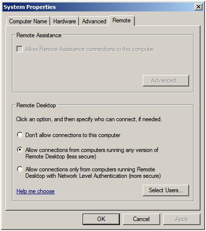
The Remote properties dialog provides a number of options. The default setting is to disallow remote connections to the computer system. The second option allows remote desktop connections from any version of the Remote Desktop client. The third, and most secure option, will only allow connections from Remote Desktop clients with Network Level Authentication support. This typically will only allow access to systems providing secure network authentication such as Windows Vista and Windows Server 2008.
If the Windows Firewall is active, the act of enabling Remote Desktop administration also results in the creation of a firewall exception allowing Remote Desktop Protocol (RDP) traffic to pass through on TCP port 3389. This default port can be changed by changing this setting in the Registry key HKEY_LOCAL_MACHINE\System\CurrentControlSet\Control\TerminalServer\WinStations\RDP-tcp\PortNumber. The easiest way to locate this registry key value is to execute regedit from the Run window or a command prompt, select Edit - > Find and enter RDP-tcp.

Controlling Remote Desktop Access

The default configuration for Remote Desktop is to allow all members of the Administration group to connect remotely. Active Directory also contains a Remote Desktop Users group to which users may be added to provide Remote Desktop access privileges. To provide users with remote desktop access, open the Control Panel -> System and Maintenance -> System -> Remote settings and click on the Select Users button to invoke the Remote Desktop Users dialog illustrated in the following figure:
Selecting Windows Server 2008 Remote Desktop Users

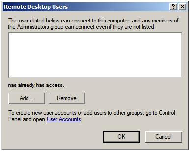
Note that users with administrative privileges do not need to be added to this list; by default they already have Remote Desktop access. To add additional users click on the Add... button to display the Select Users dialog. Enter the name of the user in the text box entitled Enter object names to select and click on Check names to list names that match the name entered. Select the appropriate name from the list. The following example shows user Bill on server winserver-2:

Selecting a user for remote access

Click on OK to apply the change. The new user will now appear in the list of users with Remote Desktop access on the Remote Users screen. Click OK to close this screen and click on Apply in the System Settings screen. The specified user will now have remote desktop access to the system.

Remote Desktop Group Policy

A vast array of configuration options for Terminal Services is available through the Group Policy settings. To access these values start the Group Policy Object Editor (open the Start menu and enter gpedit.msc into the Search box). In the Group Object Policy Editor navigate to Computer Configuration\Administrative Templates\Windows Components\Terminal Services or User Configuration\Administrative Templates\Windows Components\Terminal Services to access the range of policy settings available.
Policy options include, amongst other options, items such as control over resource redirection (printers, audio etc), setting session time limits and security settings. A complete overview of all the settings is beyond the scope of this book but almost without exception the various settings are largely self-explanatory.

Starting the Remote Desktop Client

With the appropriate configuration tasks completed on the remote system the next step is to launch the Remote Desktop Client on the local system. The client can be run in either administration mode which provides full integration with the console of the remote server, or virtual session mode which provides some administrative privileges but does not provide console access or allow applications to be installed.
To invoke the Remote Desktop Client in virtual session mode either select Start -> All Programs -> Accessories -> Remote Desktop Connection or enter the following in the Run dialog or at a command prompt:
mstsc
To start the Remote Desktop Client in administrator mode run the following command:
mstsc /admin
In either case the following initial screen will appear requesting details of computer to which the client is to connect:

Specifying the Remote Computer

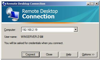
This can either be an IP address or a computer name. If previous connections have been established the User name field will be populated with the user name used in the preceding session. If you need to log in as a different user this option will be provided on the next screen which appears after the Connect button is pressed:

Windows Serevr 2008 Remote Desktop Security Screen

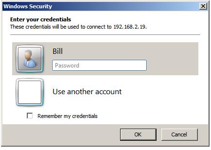
In this screen enter the password for the selected user (note that remote desktop access is only available for user accounts which are password protected). If a user other than the one displayed is required, simply click on the Use another account link and enter the necessary details. Click on OK to establish the connection. After a short delay the remote desktop will appear on the local computer screen.

Remote Desktop Client Configuration Options

The Options>> button displayed on the initial screen of the Remote Desktop Client provides six tabs, each containing a range of configuration options:
  • General - Allows login credentials to be configured and session information to be saved.
  • Display - Configures the resolution and color settings to be used when displaying the remote desktop on the local system.
  • Local Resources - Specifies which local resources (sound, disk drives, printers etc) are to be made accessible to the remote system during the Remote Desktop session. This page also provides options to control the situations under which special key combinations such as Ctrl-Alt-Del are interpreted by the local or remote systems.
  • Programs - Allows specified programs to be automatically invoked each time a remote sessions is established.
  • Experience - Controls which desktop features are enabled or disabled for the Remote Desktop session. For example, over a slow dial-up connection it is unwise to have the desktop background displayed and font smoothing enabled. Either select the connection type and speed to see recommended settings, or use Custom to configure your own settings. This particular screen also provides the option to have the connection automatically re-established in the event that a session is dropped.
  • Advanced - Enables and disables remote server verification. This ensures that the remote server to which you are connected is indeed the server you wanted. Also available are TS Gateway settings. By default the Remote Desktop Client is configured to automatically detect TS Gateway settings.

Remote Session Tracking

With Remote Desktop access implemented it is often useful to find out at times who is logged into a system. This can be achieved using the quser command-line tool. To obtain details of logged in users on a local system simply run quser at a command prompt or in a Run dialog:
C:Users\Administrator> quser
 USERNAME              SESSIONNAME        ID  STATE   IDLE TIME  LOGON TIME
 administrator                             1  Disc         3:18  7/11/2008 12:36 PM
 bill                  rdp-tcp#0           2  Active          .  7/14/2008 9:11 AM
 nas                   console             3  Active      none   7/11/2008 12:58 PM

To obtain information for a remote system simply run quser with the /server:<hostname> command-line option. For example:
C:\Users\Administrator> quser /server:winserver-2
 USERNAME              SESSIONNAME        ID  STATE   IDLE TIME  LOGON TIME
 administrator                             1  Disc         3:22  7/11/2008 12:36 PM
 bill                  rdp-tcp#0           2  Active          .  7/14/2008 9:11 AM
 nas                   console             3  Active      none   7/11/2008 12:58 PM

Logging out from a Remote Desktop Session

When the Remote Desktop Client is exited by pressing the 'X' on the control panel the remote session continues to run on the server even though no client is connected. Next time the user connects the desktop session will appear exactly as it was left before.
To end the session select Start in the remote desktop session, click on the right arrow button in the bottom right hand corner of the menu and select Log Off. This will close down the remote desktop session and close the remote desktop client.

Running Multiple Remote Desktops

Multiple concurrent remote desktops can be run and managed within a single window using the MMC Remote Desktops snap-in. This may either be snapped into the MMC or launched from the command-line or a Run dialog by typing:
tsmmc.msc
Once launched, right click on the Remote desktops item in the tree in the left hand panel and select Add a new connection from the menu. Once selected the Add New Connection dialog will appear as follows:

Adding a new connection to the Remote Desktops snap-in

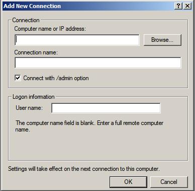
In this dialog enter the IP address or computer name of the remote system together with the User name and the name to be assigned to this connection (this is essentially the name by which this connection will be listed and administered inside the Remote Desktops snap-in). For an administrative session (as opposed to a virtual session) set the Connect with /admin box. Click OK to add the session to the snap-in. Once added, the session will appear in the left hand panel under Remote Desktops. Repeat these steps to add connections to any additional remote systems required.
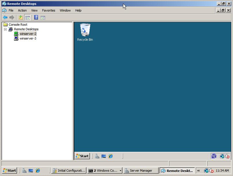
To establish a remote desktop connection, right click on the name of the session from the left hand panel and select Connect from the menu. The remote session will appear in the window. To start another session simply right click on the session name and once again select Connect. To switch between sessions simply click on the name of the session in the left hand panel and the corresponding desktop will be displayed. The following figure illustrates two sessions running in Remote Desktops:

Multiple remote desktops running in the Windows Server 2008 Remote Desktops Snap-in

To change configuration options for each session right click on the desired session in the left hand panel and select Properties. This panel has a number of tabs which enable credentials, screen size and program start properties to be defined.